

Introduction
This is the Emergency Telephone functional specification for the ET system Implemented along the expressway. The document will be divided into three portions namely Road side Equipment Hardware, Control Room Equipment Hardware and Software and Graphical user interface section.
.png)
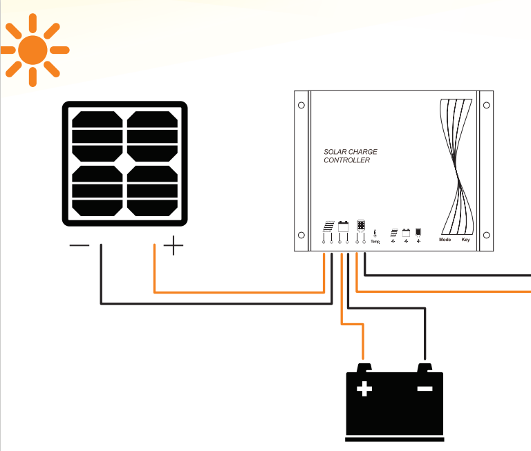
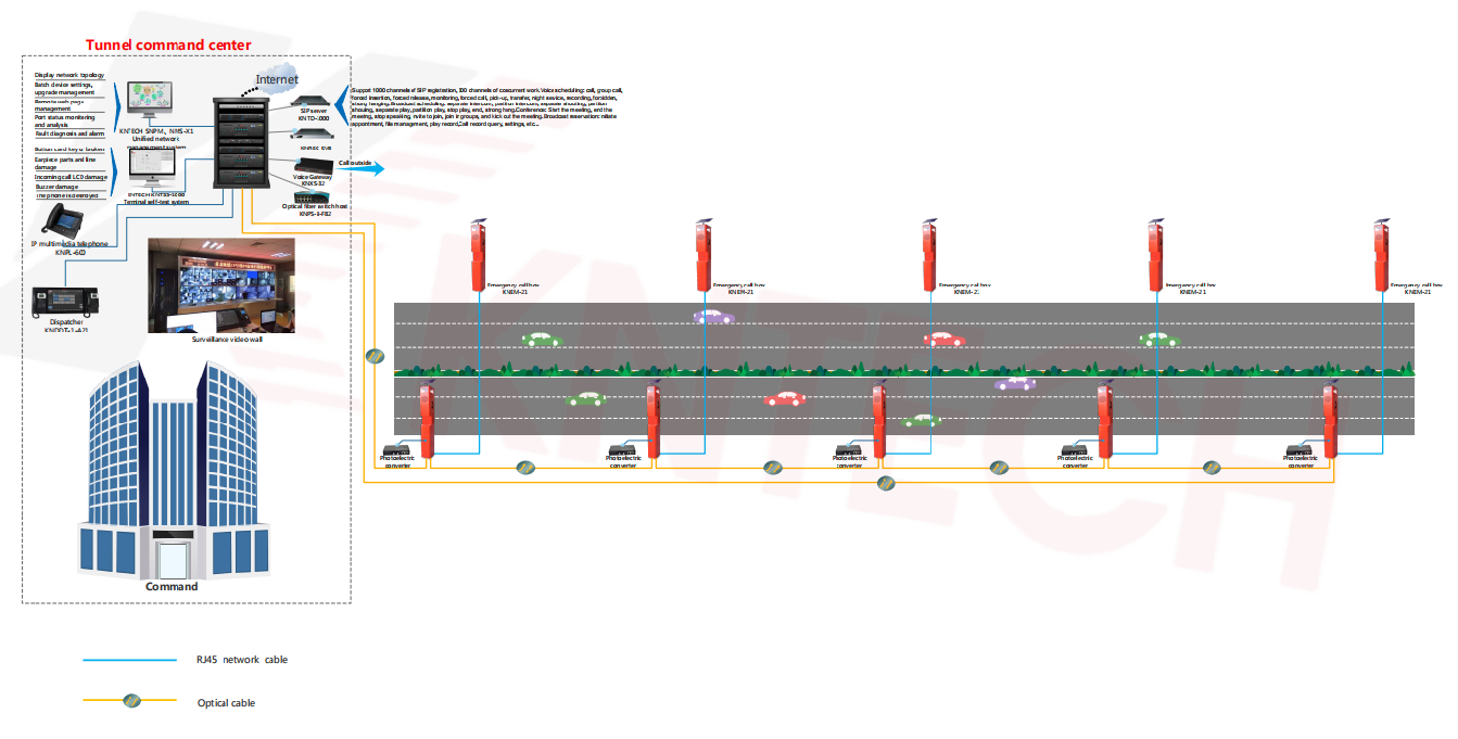
One number of the Single Mode fibre optics core will be used for all the site emergency telephone connectivity with the control room system. Each Master ET is equipped with Optical converter, (where it is the heart for the ET system) solar panel, solar charge controller, battery, Surge protection board.
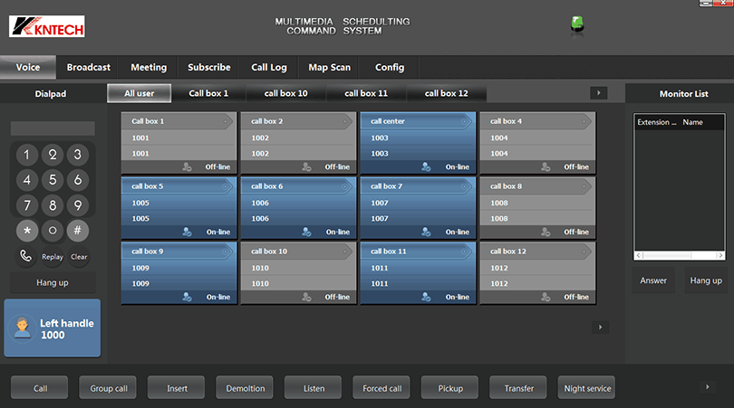
Each slave ET will be connected to the respective master ET. All the ET at the roadside are equipped with microphone, speaker and push button. When a road user makes a call from an ET, optical interface equipment(control room rack 1) will receives the signal and the Audio Matrix equipment(control room rack 1) will also receives the signal and establishes the communication between road user and operator and the recording will be started.The recorded conversation will be kept in the ET server. The operator in the control room will be equipped with Call In software to facilitate them to perform their task conveniently. The Call In software will be available on client computers. The operating system for the ET server and clients will be based on LINUX Operating System.
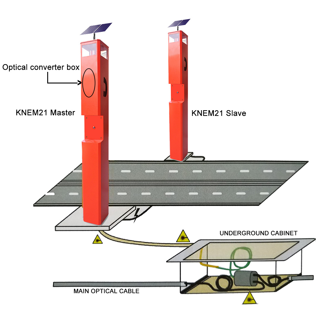
Optical converter box
Each pair of Emergency Telephone Call Box uses only one set of Optical converter box.
SYSTEM DESIGN
The whole system is generally leered in two locations:
a. Roadside
b. Control Room
Equipments that are involved at Roadside:
| Item | Description | Functionality |
| 1 | Emergency Call Box(ECB) | To mount caller interface equipment |
| 2 | Speaker and Microphone | To allow voice reception and dissemination. |
| 3 | Push button | To activate the system and alert the Control Cemre Operator |
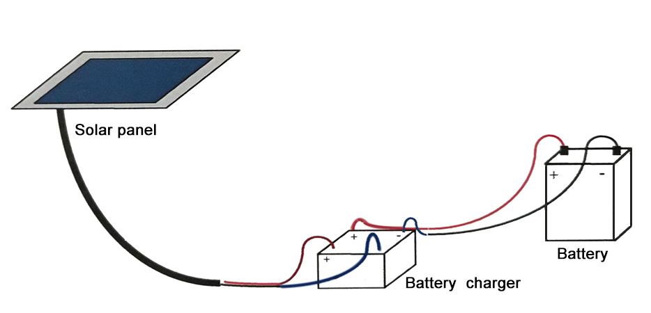
| 4 | Solar Power System | Consist of solar panel, batery changer and battery |
| 5 | Opcical Interface | Fibre Based data and voice transmission electromic equipment |
The Control Centre Unit:
Functional Deseription
1.Location and identification of calling ECB
2.Telephone communication control (put on hold, return to call, end of commucation)
3. Ringing when an ECB is calling
4. Visual indication of calling ECB number
5.Queue control
6. Automatic or manual test of ECB, setting
7.Operating status of ECB (audio, on hold, stand-by, out of order).
8.Call time recording
9.Call transfer to another operator, 3 person conference communications.
10. Automatic dialling of emergency service
11. Automatic display of ECBOB and Central Control equipment status and alarms
13. Conversation recording and tracing(with recorder option)
The master ECB contain ECBOB, solar panel, battery charger, battery, a speaker, a microphone and a push button and slave ECB contain a speaker, a microphone and a push button.
SOLAR POWER SYSTEM
Microphone, speaker and push button positions in ET
Speaker and microphone specifications
| Description | Characteristic |
| Speaker | |
| Audio output level | (0 to 5)W |
| Loudspeaker Impedance | 8 Ohm 5W |
| Microphone | |
| Type | Electro Dynamic Microphone |
Battery specifications
| Description | Characteristic | |
| Nominal Voltage | 12 V | |
| Rated Capacity | 22 AH | |
| Capacity | 20 hour rate(900 mA) | 18.0Ah |
| 10 hour rate(1620 mA) | 16.2Ah | |
| 5 hour rate(2000 mA) | 10.0Ah | |
| Internal Resistance | Full Charged Battery | ≤190 mΩ |
Solar Panel Specifications
| Description | Characteristic |
| Nominal Voltage | 18 V |
| Power supply | 40 W |
| Size | 520 * 500 * 20 (MM) |
SOLAR CHARGE CONTROLLER
| Description | Characteristic |
| System Voltage | 12V |
| Max Load current | 10A |
| Dimensions | 82 x 58 x 20mm(w x hx d) |
| Self consumption | 10mA |
| Final Charge Voltage | 13.8V |
| Type of protection | IP68 |
System standby: 32 Hours after full charged
System Audio mode time: 17 hours after full charged.
EM21 Main unit VoIP telephone Specifications :
VoIP SIP2.0 telephone DTMF dialing Audio Codes:G.711, G.723,G.726, G.729
MTBF:100000hours MTTR: 2 hours Network:10/100 BaseTX Ethernet, RJ45
Hot-line (maximum length of each number is 16 digits) connectors, Cat5e or better
Communication: Full duplex 2-way hands-free IP Protocols:IPv4, TCP, UDP, RTP, DHCP, SIP
communication 1 x LAN Protocols:Power over
Call Control Signaling:VOIP SIP Info(DTMF), RFC Ethernet(PoE,802.3af),
2833(DTMF) 1x LAN(IEEE 802.3af), Network Access
Power:Power over Ethernet, IEEE802.3af, Class 0 Control(IEEE 802.1x),STP(IEEE 802.1d),
Local power, 12VDc,Idle 2W, Max 10W RSTP(IEEE 802.1d-2004)
Auxiliary Contacts: (option)
1 Aux Output, dry contact programming and configuration through Web GUI
Contact Ratings. Load: Resistive load
Rated load:0.3 A at 125 VAC; 1 A at 30 VDC remote automatic software upgrade, centralized
Rated carry current:1A monitoring.
Max.switching voltage:125 VAC,30VDC Echo cancellation code:G.167/G.168
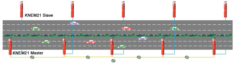
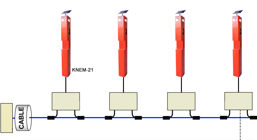
System topology
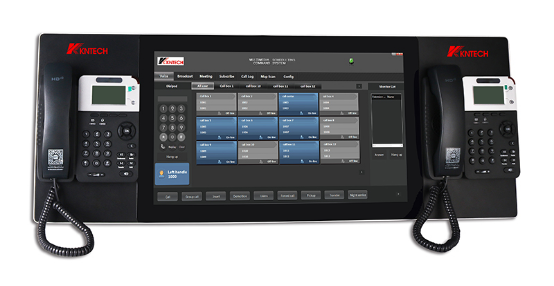

Application
.png)
.png)
.png)
Thank you for reading, if you have any questions or needs, please contact us!
EMAIL: marketing@koontech.com, we will reply you immediately