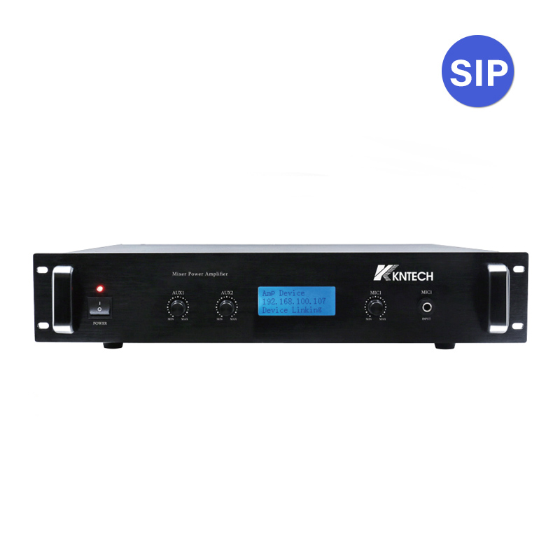
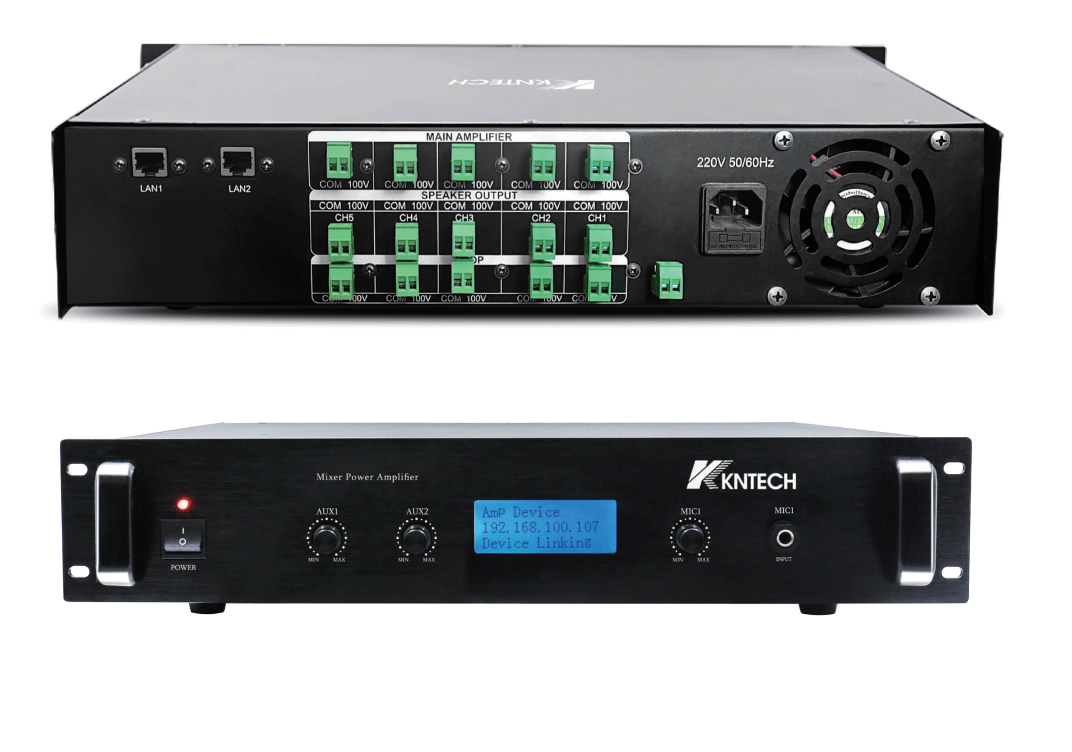
This remote VolP amplifier units is lP-based power amplifier, The units is connected to the central exchange unit via ethernetCopper CAT5 or CAT6 or filber cable.The amplifier is a Class D power amplifier due to its especially high eficiency, low poweconsumption and long life.
The remote lP-based power amplifier is integrated speaker monitoring. Speaker circuits are to be continuously monitored forshort circuit, earth leakage, and line inter ruption, Speakers is allowed navigation through the intuitive user interface. The useris be able to define settings and make changes using the integrated web interface.
VolP SIP 2.0
lP amplifier Self-diagnosis.
Line Monitoring between amplifier and intercom server and speakers
Display and function keys at the front of the unit
Each unit has only one independent audio channelln telligent 5+1 backup control
Freely program mable
Integrated monitoring functions (short circuit, excess temperature, voltage failure, function monitoring)
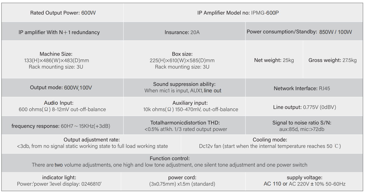
Distortion factor < 0.5% at rated power
Optimized according to the EN 60849 standard "Sound systems for emergency purposes"Upon special requirement.
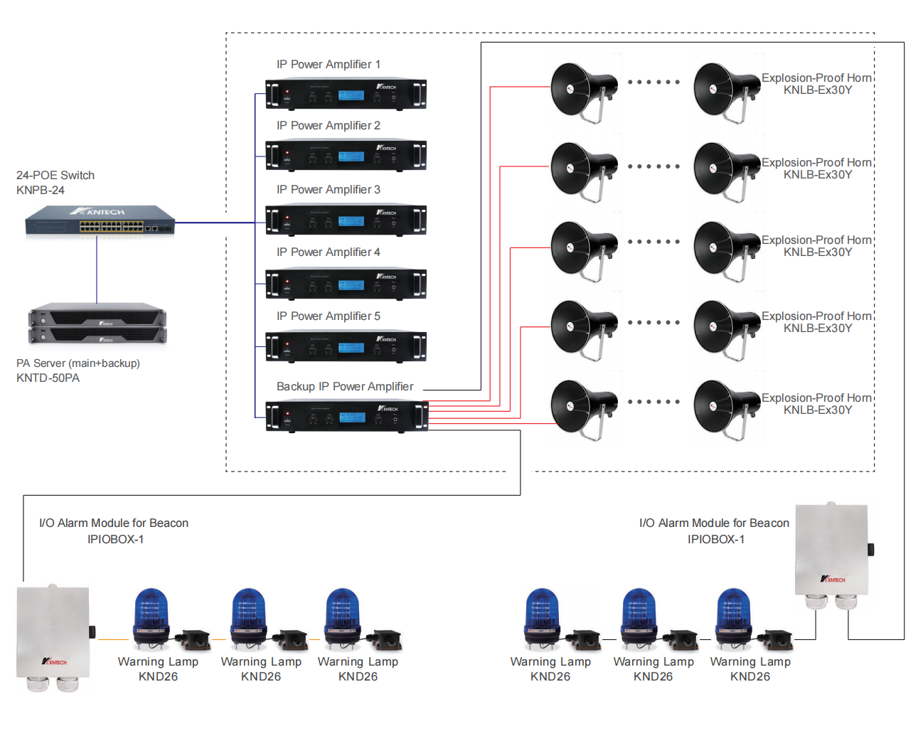
1. The power amplifier combination can be 1 main + 1 backup, 2 main + 1 backup, 3 main + 1 backup, 4 main + 1 backup, 5 main+1backup, up to 5 main +1 backup; Flexible collocation;
2. When each IP main power amplifer is playing diferent audio sources, the backup power amplifier can replace any damagedmain power amplifier at any time, whichever fails first, When the bad power amplifier returns to work, the spare power amplifielcan replace another damaged power amplifier.
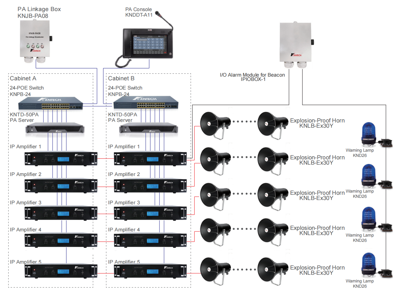
1. A/B system host active backup hot backup.
2. A/B active and standby power amplifier hot backup.
3. The speaker cable is connected to the spare power amplifier. The main power amplifier works normally.
When the main power amplifier fails, it will automatically switch to the backup power amplifier.
4. All power amplifiers are IP power amplifiers.
5. The dispatcher and the main and backup IP power amplifiers are automatically connected to the A/B host, and
when the A host fails, it will automatically switch to the B host.
6. The warning light control box supports that when the broadcast is started, the warning lights are turned on, and
when the broadcast is ended, the warning lights are turned off.
7. A single smart speaker uses the original audio circuit to perform fault self-detection and report actively.
8. Speaker circuit loop detection.

 English
 中文版
中文版 français
 русский
 Español
 عربى
عربى